· Steve Grice · 2 min read
How and Why to Use a Logic Analyzer

A logic analyzer lets us look at the digital data coming out of ports on various devices, in much the same way an oscilloscope lets us look at analog signals. In this lesson, we plug our logic analyzer into an Arduino’s serial port to show how we can record and analyze digital data.
Parts List
KeeYees Logic Analyzer (~$14)
Arduino UNO (~$30)
Jumper Cables (~$7)
As an Amazon associate I earn from qualifying purchases.
Timestamps
- 0:00 Intro
- 0:28 Parts list
- 1:06 Arduino code
- 1:59 Arduino wiring
- 2:24 Logic analyzer in action
- 3:27 Outro
Arduino Code
We use the following simple program on our Arduino, which outputs a message via serial every 2 seconds:
void setup() {
  Serial.begin(9600);
}

void loop() {
  Serial.println("Hello world!");
  delay(2000);
}
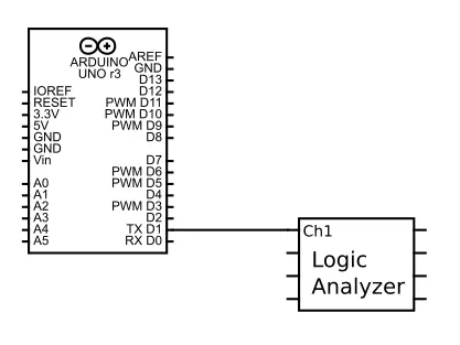
Arduino Wiring
We wire channel 1 of the logic analyzer to the TX port of the Arduino. To do this, we use a female-to-female jumper (which should come with the logic analyzer) and a (more common) male-to-male jumper to complete the connection.
With this wiring in place, we can launch the software that came with the logic analyzer and perform a capture, which will show us the “Hello World” message coming through Channel 1!
This same technique can be applied to a variety of protocols, such as I2C, SPI, PS2 Keyboard/Mouse, and USB (low- and full-speed only).